Controls from two to four digital output stages and maintains a staging delay between stages turning on, and between stages turning off.
Digital output stages are typically used to control heating and cooling where multiple heating elements or cooling stages can be switched on and off as required. The elements or stages do not increase their output gradually. Instead they are controlled only by on and off signals.
The DigitalStagesDelay property ‘Stages’ provides control of the number of stages. The properties Stage1On, Stage1Off, Stage2On, Stage2Off, Stage3On, Stage3Off, Stage4On and Stage4Off control the specific thresholds (usually percentages) at which the respective stages will turn on and off. Note that you only need to enter on and off values for the stages that your system requires. The input values ‘MinOn’ and ‘MinOff’ control the duration of the delays and can be set by the user or left at their default values.
Table 7 shows examples of input values that turn up to four stages on and off. For example, when configured with four stages, Stage 1 turns on at an input value of 20.0%; and off at an input value of 0.5%, Stage 2 turns on at an input value of 45.0% and off at an input value of 30.0%, etc.
Notice that the input values that turn off the stages are not the same as the values that turn on the stages. This difference provides an effective deadband. For example, Stage 1 will only turn on when the input reaches 20%. Once turned on the stage will not turn off until the input reaches 0.5%. The state of the output remains unchanged over input values from 0.5% to 20% thus creating a deadband over that range.
Table 7: Example of On and Off Values for Stages Configured with DigitalStagingDelay
Stages |
Stage 1 ON |
Stage 1 OFF |
Stage 2 ON |
Stage 2 OFF |
Stage 3 ON |
Stage 3 OFF |
Stage 4 ON |
Stage 4 OFF |
2 |
40.0 % |
10.0 % |
90.0 % |
60.0 % |
- - |
- - |
- - |
- - |
3 |
26.6 % |
6.666 % |
60.0 % |
40.0 % |
93.0 % |
73.3 % |
- - |
- - |
4 |
20.0 % |
0.5 % |
45.0 % |
30.0 % |
70.0 % |
55.0 % |
95.0% |
80.0 % |
Figure 21: Digital Stages Turning On as Input Increases
Figure 21 shows four digital stages turning on as the input signal increases. Each stage is shown as an addition to the overall heating or cooling effort. Remember that if the input signal were decreasing, the input values triggering the stages off would be different than the input values that had triggered the stages on.
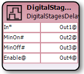
Inputs |
||||
|---|---|---|---|---|
|
Slots |
Type |
Default |
Description |
|
In |
Numeric |
Null |
The input to the block in percent. |
|
MinOn |
Integer |
60 |
The minimum on time (in seconds) between turning stages on. |
|
MinOff |
Integer |
30 |
The minimum off time (in seconds) between turning stages off. |
|
Enable |
Digital |
True |
Enables or disables the block. Disabling the block turns off all digital outputs and cancels any staging timers. |
Outputs |
|||
|
Slots |
Type |
Description |
|
Out1 |
Digital |
First digital output to stage. |
|
Out2 |
Digital |
Second digital output to stage. |
|
Out3 |
Digital |
Third digital output to stage. |
|
Out4 |
Digital |
Fourth digital output to stage. |
Properties |
||
|
Slots |
Description |
|
Stages |
Sets the number of outputs to stage. See Table 7. |
|
StageXOff |
The threshold (percentage) at which the respective stage will turn off. |
|
StageXOn |
The threshold (percentage) at which the respective stage will turn on. |