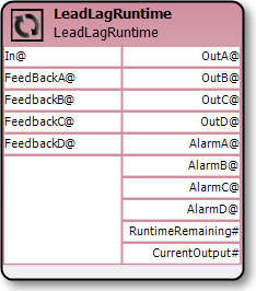
The LeadLag block outputs a digital value of True on one of four Out slots when In is set to True which will “rotate” output to the next Out slot when either the corresponding Feedback input slot transitions to False and remains False for the specified FeedbackDelay, or the runtime of the current Out slot exceeds the specified MaxRuntime.
This block can be used for example, to rotate between pumps where each pump’s status is connected to each FeedBack slot, and each pump is connected to the corresponding Out slot. Note that if a pump goes down and remains down causing the corresponding Feedback input slot to be False, the Out slot for that pump will continue to output a value of True until the Feedback slot becomes True (e.g. to allow for troubleshooting of the pump).
The MaxRuntime value can be used to force a rotation to the next Out slot after the specified number of hours (e.g. to ensure even distribution of runtime between pumps).
The respective Alarm Slots will be set to True when a Feedback slot has not been set to True within the specified FeedbackDelay (e.g. if a pump goes down).
Inputs |
||||
|---|---|---|---|---|
|
Slots |
Type |
Default |
Description |
|
In |
Digital |
False |
When set to True, the block will turn on the next Out slot when the current Feedback input slot transitions to and remains false for the specified FeedbackDelay, or the runtime of the current In slot exceeds MaxRuntime. When set to False, all Out slots will be set to false. |
|
FeedBackA |
Digital |
False |
The first input slot for the block to monitor. |
|
FeedBackB |
Digital |
False |
The second input slot for the block to monitor. |
|
FeedBackC |
Digital |
False |
The third input slot for the block to monitor. |
|
FeedBackD |
Digital |
False |
The fourth input slot for the block to monitor. |
Outputs |
|||
|---|---|---|---|
|
Slots |
Type |
Description |
|
OutA |
Digital |
The first output slot that the block will set the signal on. |
|
OutB |
Digital |
The second output slot that the block will set the signal on. |
|
OutC |
Digital |
The third output slot that the block will set the signal on. |
|
OutD |
Digital |
The fourth output slot that the block will set the signal on. |
|
AlarmA |
Digital |
The alarm that will be set to True when the first Feedback input has not transitioned to True within the specified FeedbackDelay |
|
AlarmB |
Digital |
The alarm that will be set to True when the second Feedback input has not transitioned to True within the specified FeedbackDelay |
|
AlarmC |
Digital |
The alarm that will be set to True when the third Feedback input has not transitioned to True within the specified FeedbackDelay |
|
AlarmD |
Digital |
The alarm that will be set to True when the fourth Feedback input has not transitioned to True within the specified FeedbackDelay |
|
RuntimeRemaining |
Integer |
The remaining runtime, in seconds, for the current Out slot. When the time runs out the block will set the current Out slot to False and the next Out slot to True. |
|
CurrentOutput# |
Integer |
The current Out slot. |
Properties |
||
|---|---|---|
|
Slots |
Description |
|
FeedbackDelay |
The time, in seconds, in which the current FeedBack input slot must transition from False to True, otherwise the corresponding Alarm will be set to True. |
|
MaxOutputs |
The number outputs for which inputs should be monitored and used by the block to set the outputs. |
|
MaxRuntime |
The runtime, in hours, that each Out slot should be run for (i.e. the number of hours each Out slot should remain True before being set to False). |
|
Persistent |
When set to True, the current “lead output” and the accumulated runtime number are maintained between program restarts. |