This section describes the configuration of the AnalogInput functional block. For digital configuration, see DigitalInput Tasks.
All inputs on the UHC-400 are Universal Inputs (UI) and are fully configurable through software. Both analog inputs and digital inputs use the UI functional block.
Through the UI functional block you can:
▪Define the UI type as digital, voltage, current or resistive
▪Select the associated network variable type
▪Set the communication settings
▪Choose a linearization table for scaling and offset adjustments
To configure the UI functional block:
1
1.On the AnalogInput, click the SmartTag. From the menu click ‘Configure Functional Block’. The functional block will open.
2.As an option, enter descriptive text in the ‘Description’ box. Text that links the input to the input signal source may be useful. For example, ‘Foyer Temperature’.
3.Beside ‘Point type’ click the drop down arrow to select the hardware signal type that will be connected with the UI.
4.Beside ‘Network variable type’ click the drop down arrow to display the available network variable types for the chosen point type. Use the drop down list box to select the standard network variable type that is appropriate for your application.
5.Beside ‘Network variable format’ click the drop down arrow to display the available network variable formats for the chosen Network variable type.
6.In the area titled ‘Communication Settings’, set the timers associated with the UI’s output network variable. These timers determine the update behavior of the output network variable associated with the UI functional block, when it is bound to one or more input network variables. See Network Variable Transmit Control on page for a description of these settings.
7.The field ‘Digital’ is disabled when the point type is set to an analog point type.
8.The area titled ‘Analog’, displays the point type name, a filter selection, and a linearization table. The linearization table values have been created according to the hardware point type and network variable type that you chose. The linearization table contains two columns: ‘Input’ and ‘Engineering’. See Figure 23.
Figure 23: Analog Area of UI Functional Block
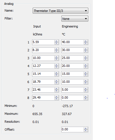
Input |
The values in the column ‘Input’ display the scale of the actual signal reading at the input point. The units of measurement are displayed below the heading, ‘Input’. The plug-in supplies these values and units based on your selection from the ‘Point type’ drop down list. |
Engineering |
The values in the Engineering column display the scale of the network variable type you selected in the ‘Network Variable type’ list box. The values in the column indicate the value in engineering units. The units are displayed under the column heading, ‘Engineering’. |
The table can be customized for different sensors. See ‘About AnalogInput Linearization Tables’.
9.Click the Filter button and select Low, Medium, or High according to the information below:
Filter setting |
Calculation of value supplied by input point |
None |
The value supplied is the most recent sample. |
Low |
The value supplied is 1/2 of the most recent sample plus 1/2 of the previous value. |
Medium |
The value supplied is 1/4 of the most recent sample plus 3/4 of the previous value. |
High |
The value supplied is 1/8 of the most recent sample plus 7/8 of the previous value. |
By filtering the signal supplied to an input point you can remove unnecessary fluctuations due to electrical noise or an erratic sensor.
10.For your information, the software displays the following:
Minimum, Maximum |
The limits allowable for the chosen input and network variable type. |
Resolution |
The number of decimal points available plus the minimum change supported. |
11.Enter a value in the Offset box according to the following definition:
Offset |
Specifies a constant amount that is added to or subtracted from the sampled and filtered value from the sensor after it has been converted to engineering units. The offset can be zero, or positive, or negative. |
See also: